FY6900 OCXO
Once you've started to experiment with radio transmitters and receivers, you quickly end up at a point, where you need a known good signal source for testing.
You can usually get a slightly used, but working, HP 3312A for 300€ on eBay. I'm not joking. I wish I was. At the time of writing these fully analogue function generators, that were all build decades before I was born, go for nearly the same prices as e.g. the modern Siglent SDG1032X.
So let's not do that. Instead, you can just wait until somebody drops three broken 3312As into your lap and subsequently spent many evenings nursing those amazing, but thoroughly confusing analogue artworks back to health. I even got two of the original manuals in mint-condition.
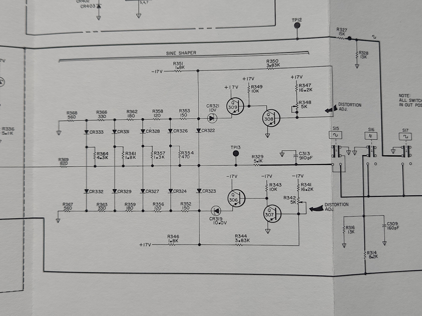
While those old instruments can usually be repaired by replacing some basic worn-out discrete components, and doing so apparently makes for a great CuriousMarc video, I wouldn't necessarily recommend that route. (That is unless you fancy spending a half a night wondering what drugs they were handing at HP back in the day.)
So you should get the Siglent. That would be expensive but reasonable, and it would just work.
Or... hear me out on that... you could head over to AliExpress or eBay and a get a FY6900 to modify it. It will cost you less than half of the Siglent. After making some minor improvements to it, it will hopefully still be cheaper but just as nice as the proper one.
Let me level with you: I don't have to justify myself for going straight for the hacky solution. I had a bigger project to procrastinate and procrastinate it I did. No yak shall go unshaved. Furthermore, I would like to remind you, that you dear reader clicked on this article about hacking a cheap Chinese instrument, so you are probably in no position to judge.
So I got one from AliExpress. Fresh out of the box the performance is okay..ish.
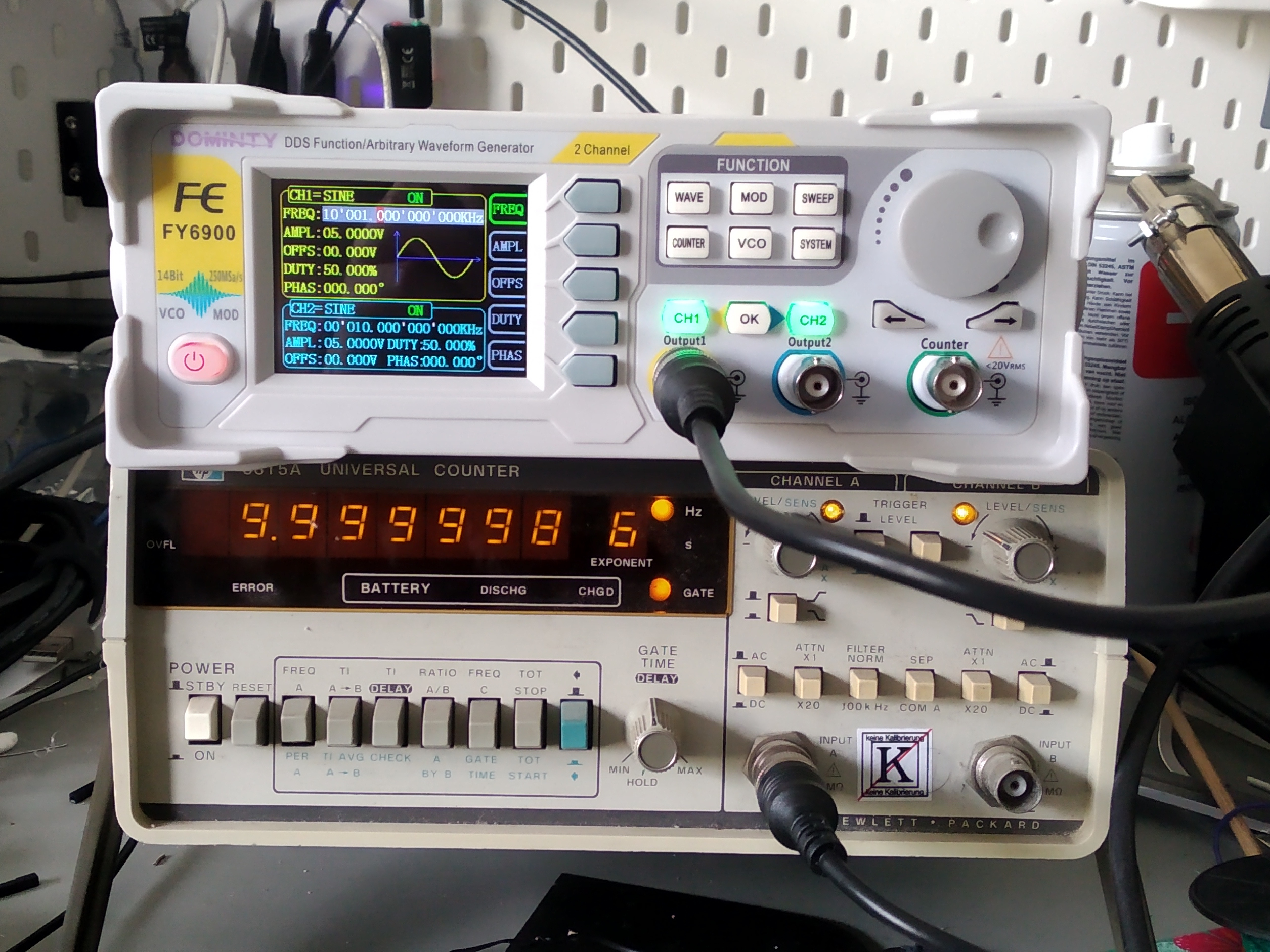
It could be a lot worse. Only 1kHz off according to the counter that has last been calibrated over 20 years ago.
Pretty sure there is some compensation for that in some Menu.
After messing a little bit with the OSCI-Setting and trying the spectrum analyser instead of the counter,
because it has been calibrated in this decade, the generator appeared fairly spot on.
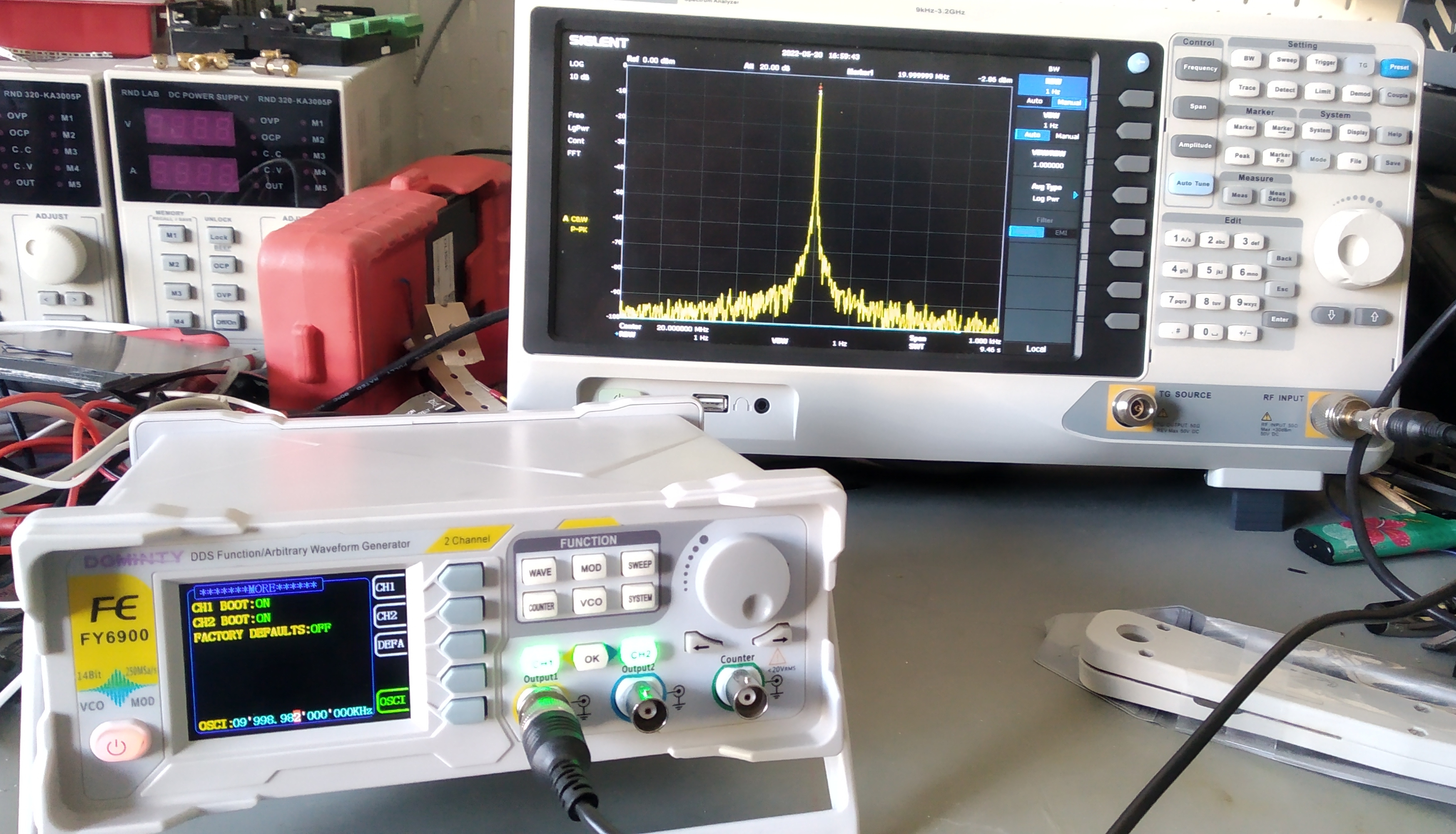
Sine setting is reasonably clean, it has decently low harmonics and a lot less weird sidebands,than I expected. Until I opened the window, and it started wandering all over the place. The temperature stability is basically non-existent. Fortunately this is something that can be fixed without too much effort.
So let's take a look inside. There is one central screw in the bottom of the unit. After undoing that, the front and back can be unclipped and finally the upper half the housing can be lifted away.
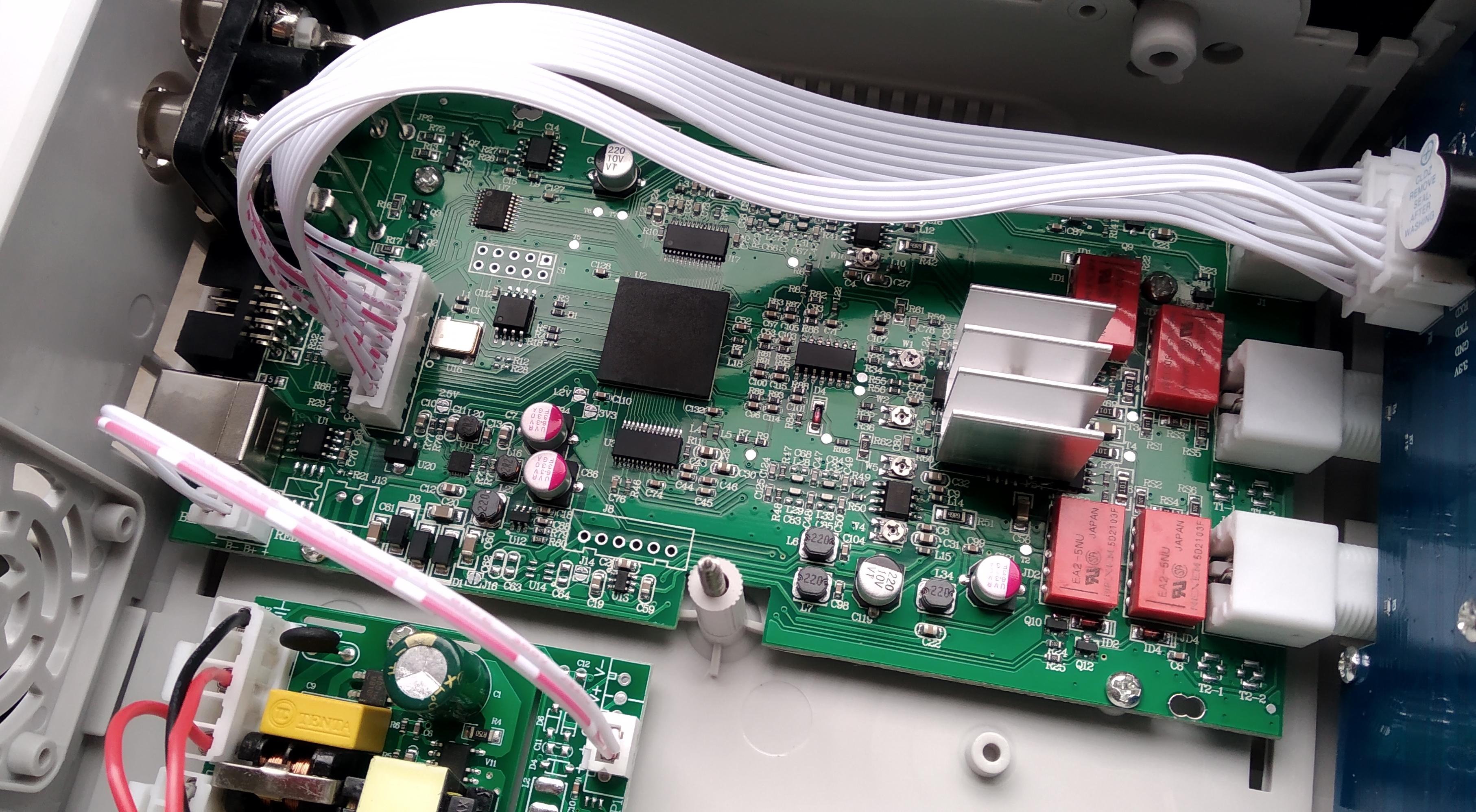
And here's our problem. Right next to the cable connecting to the display PCB is a small, probably cheap, crystal oscillator, just hanging out in the breeze of the non-existing cooling fan. A quick prodding with an oscilloscope revealed that it outputs a 10MHz rect with a maximum voltage of 3.3v. I just so happened to have something else that outputs a 10MHz rect, although it used a 5v level signal. Also, it didn't fit on that SMD footprint.
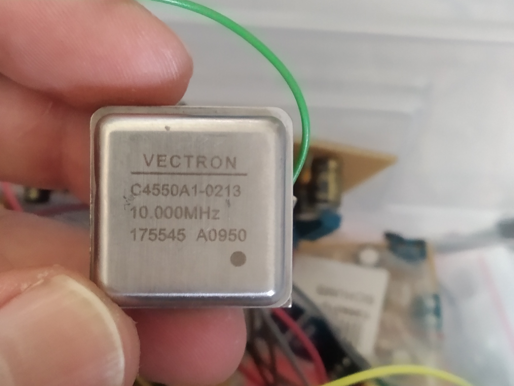
The Vectron C4550A1-0213 has been used in a lot of networking and telco equipment, which now gets slowly phased out. This means there is steady flow of slightly used surplus oven controlled crystal oscillators into your favourite online marketplace. You can usually pick them up slightly dented for less than 10€ with bits of the original PCB still attached. Over the years I bought about 10 of them from different places, and so far they all worked and were within spec.
I quickly put one on a piece of perfboard, together with a U74HC14L that acts as Schmitt-trigger for signal conditioning,
as well as a buffer to decouple the OXCO output from capacitive load and a level shifter from 5v to 3.3v output.
There is just enough unused space behind the power supply to perfectly fit this board.
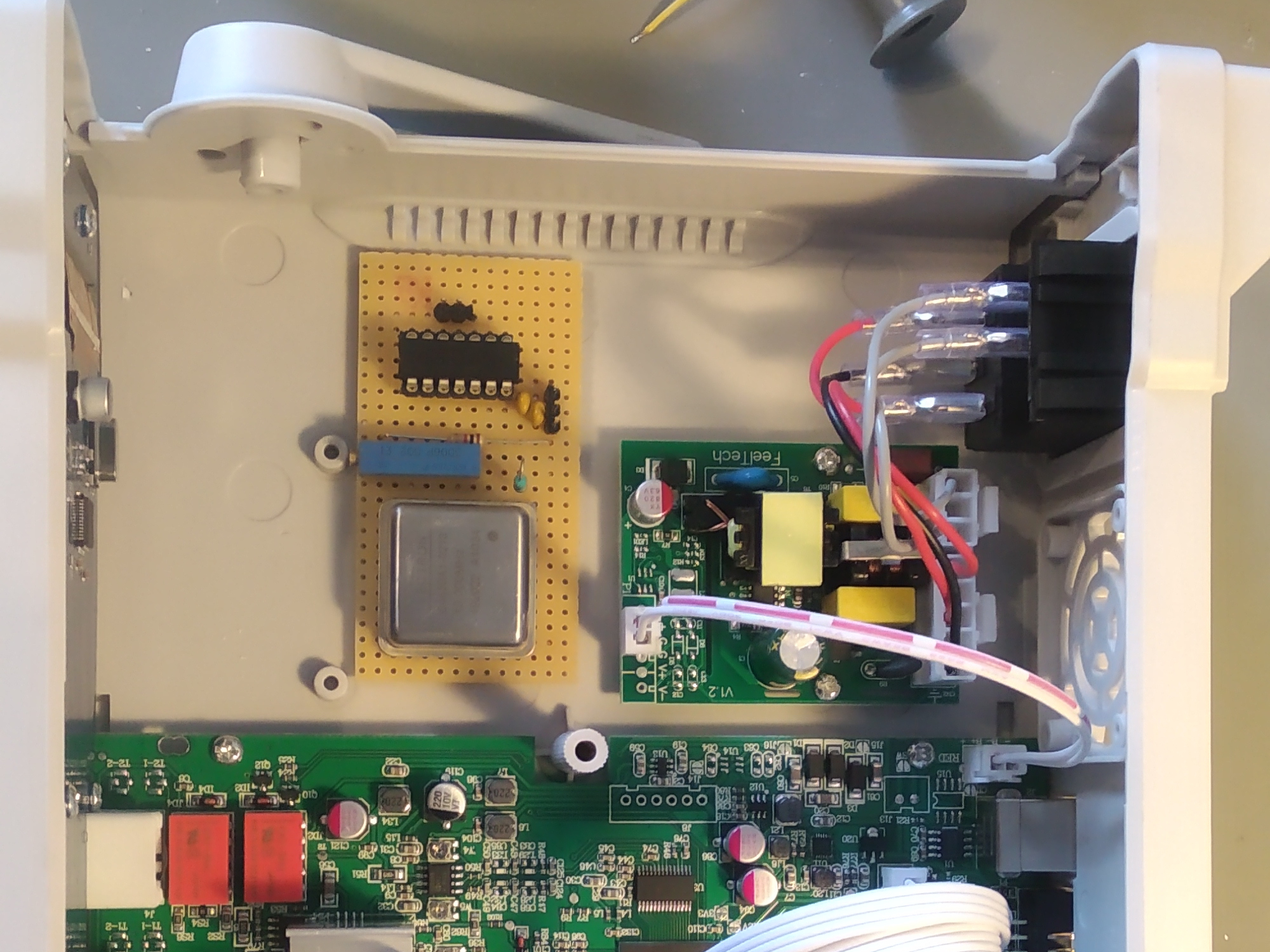
The original oscillator was unsoldered carefully using a hot air. After that it is relatively straight forward to solder a piece of micro coax to its pads.

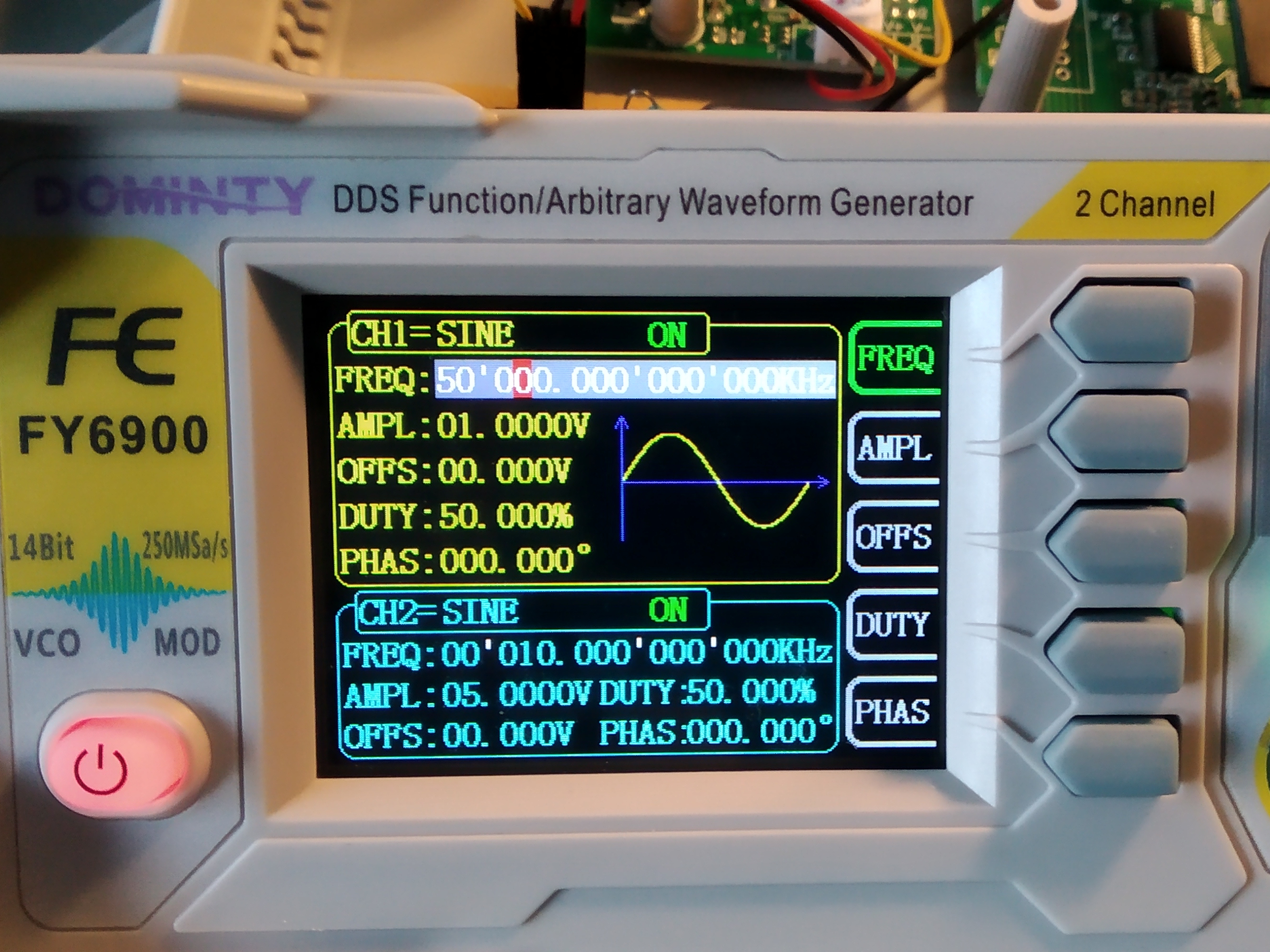
Fortunately, you can steal 5v and GND directly from the power supply output pins, there are even some unused solder pads prepared for you. 3.3v is a little more tricky. The cleanest solution I found was to solder to the 3.3v pad of the front panel connector. First tests with this new prototype were promising, the frequency was a lot more stable. It was also consistently off by the same few hertz after powering off and on again (and giving the oven some time to warm up of course). Since I didn't have an actual frequency normal at hand I decided to tune it to the reference of my spectrum analyser.
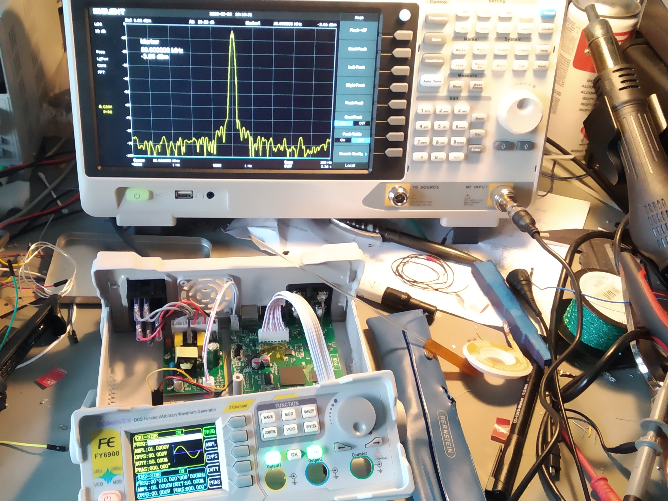
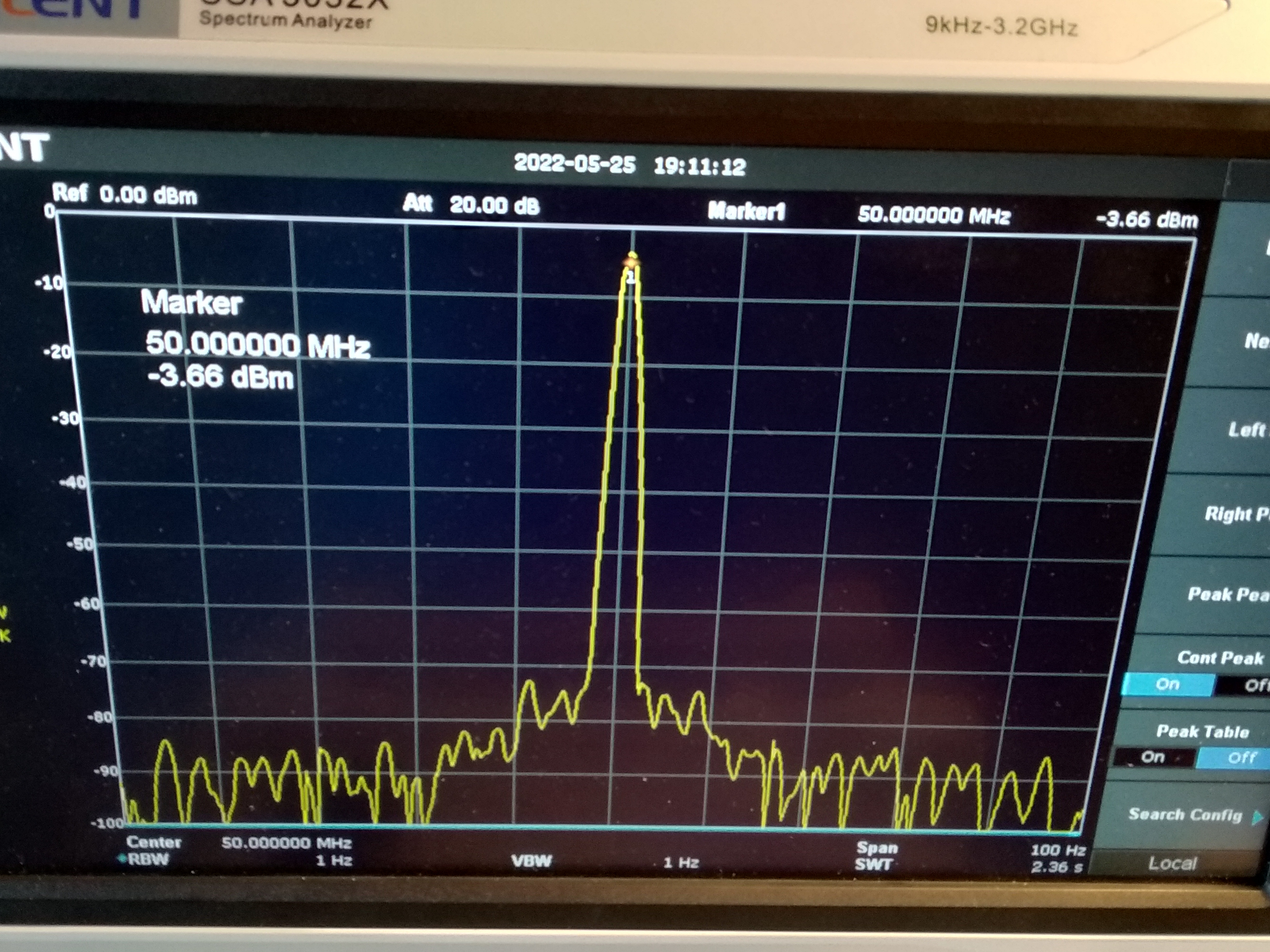
Unsurprisingly tweaking the trimmer potentiometer with a metal screwdriver is not the best idea. The screw of the trimmer is connected to one of the contacts and attaching a bit of conductive material, also known as screwdriver, to it, is effectively attaching an antenna to the to OCXOs frequency tuning pin. In the best case I would only get some weird sidebands that made it through the PLLs into the output signals. In the worst case the signal would be exactly on frequency and run away as soon as the screwdriver was removed. As a workaround you can use the little plastic screwdriver that you got with oscilloscope probes. Or if you are feeling fancy, like I did, break out the fancy plastic screwdrivers with ceramic blades.
Now that the prototype was working, I could continue to build a "proper" OCXO add-on board.
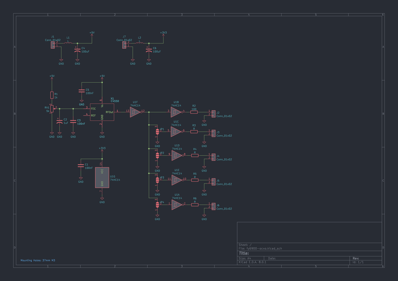
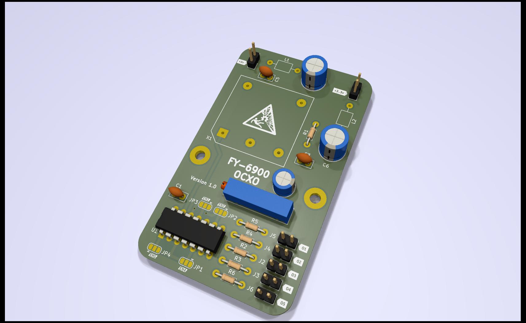
If you are interested in the gerbers or the CAD files, I've recently updated all the files to KiCAD 8 and uploaded it to my forgejo instance: forgejo.zenerdio.de/sebastian/fy6900-ocxo.
It is pretty much the same thing as the perfboard prototype. It has an input header for 5v and 3.3v. Both voltages are filtered using a series inductor and parallel capacitor. I chose 1uH and 100uF pretty much because that's what I still had leftover from another project. Exact values aren't too critical here, all those filters do is keep higher frequency stuff from the generator sneaking in the OCXO output and vice versa. As far as I can tell, those values work reasonably well for this. However, keep in mind that I've never actually done any measurements to verify of that. It's a lot of work to do properly, and the output looks fine, so either it works as intended, or there never as an issue to begin with.
The frequency error correction pin of the C4550A1 is attached to the centre tap of a multi-turn trimmer and a 1uF as well a 100nF to ground. I wanted to be extra sure that the voltage at this pin is as stable as possible, regardless of what's happing on the power rails. It might be worth adding a some form of voltage reference (z-diode, actual voltage reference chip...), but then again this is an add-on to a cheap little function generator, not some high precision GPS-disciplined reference oscillator. Keeping it from producing weird side tones in the generators output is probably enough.
The signal conditioning is still handled by a 74HC14. The first Schmitt-trigger unit turns the output of the OCXO into a clean rectangle signal. After that the other units are abused as distribution amplifiers. Having more than one output allows to use the board for other things as well, as the PCB-factory sends you 5 or 10 boards anyway and I don't plan on converting more than one cheap signal generator. The inputs to each output stage can be connected to the first stage or ground via a solder jumper. Unterminated outputs oscillating at 10MHz turn the output stage into a transmitter, with lots of juicy harmonics. If the inputs were left floating, they would just couple to the signal on the pins next to it, likely resulting in some form of self oscillations. The series resistors in the output path allow for some basic impedance matching, should it be required.
The PCB also has mounting hole that exactly fit the unused posts that the signal generator manufacturer placed next to the power supply.
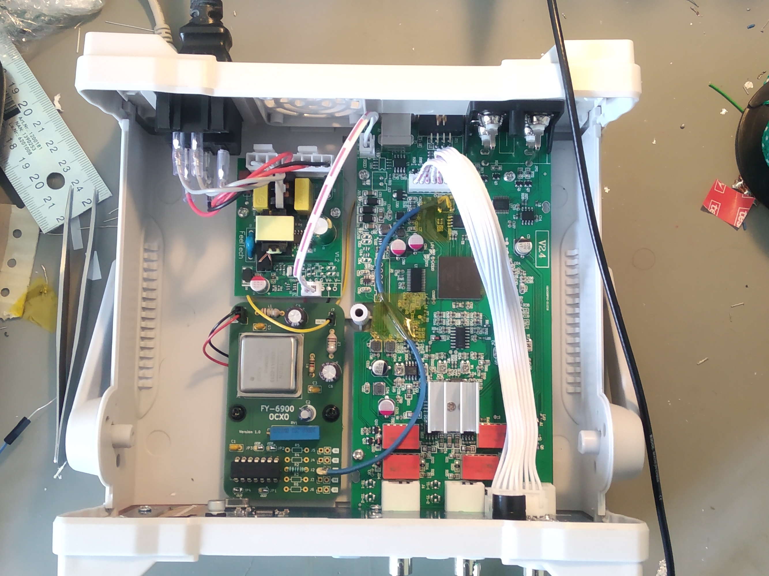
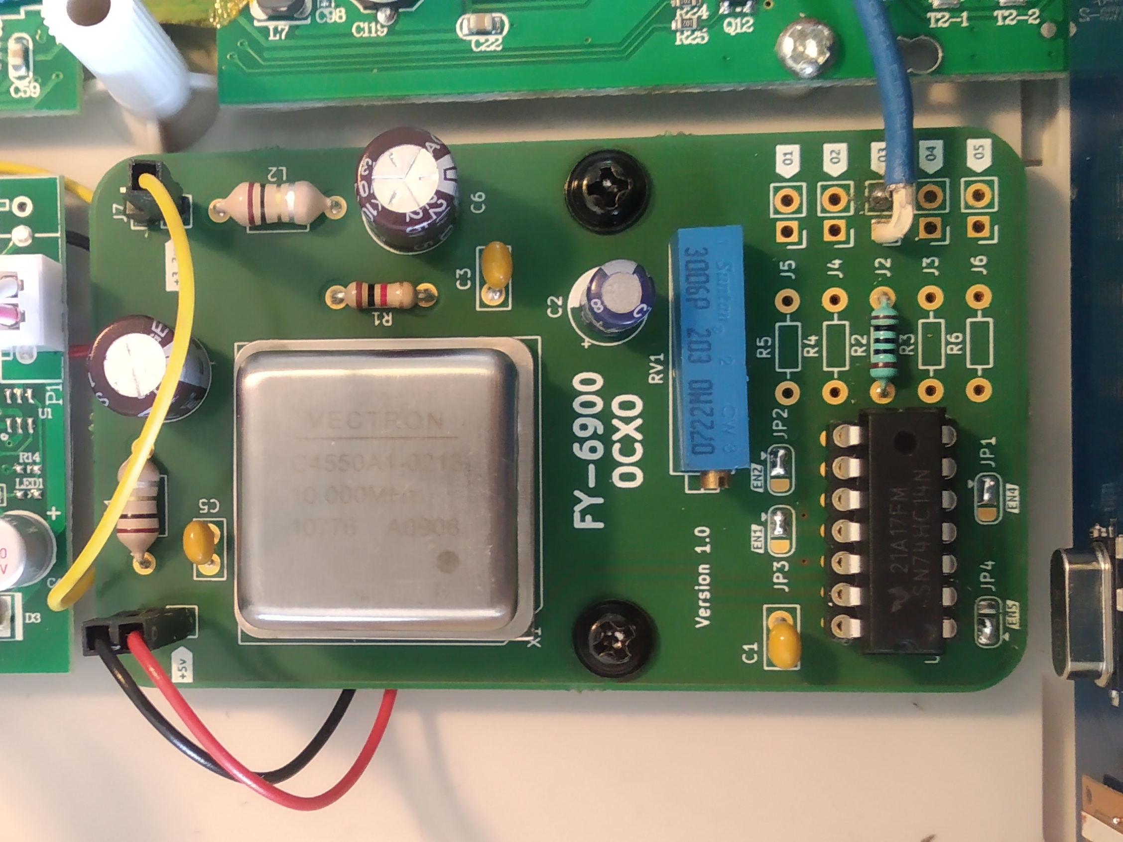
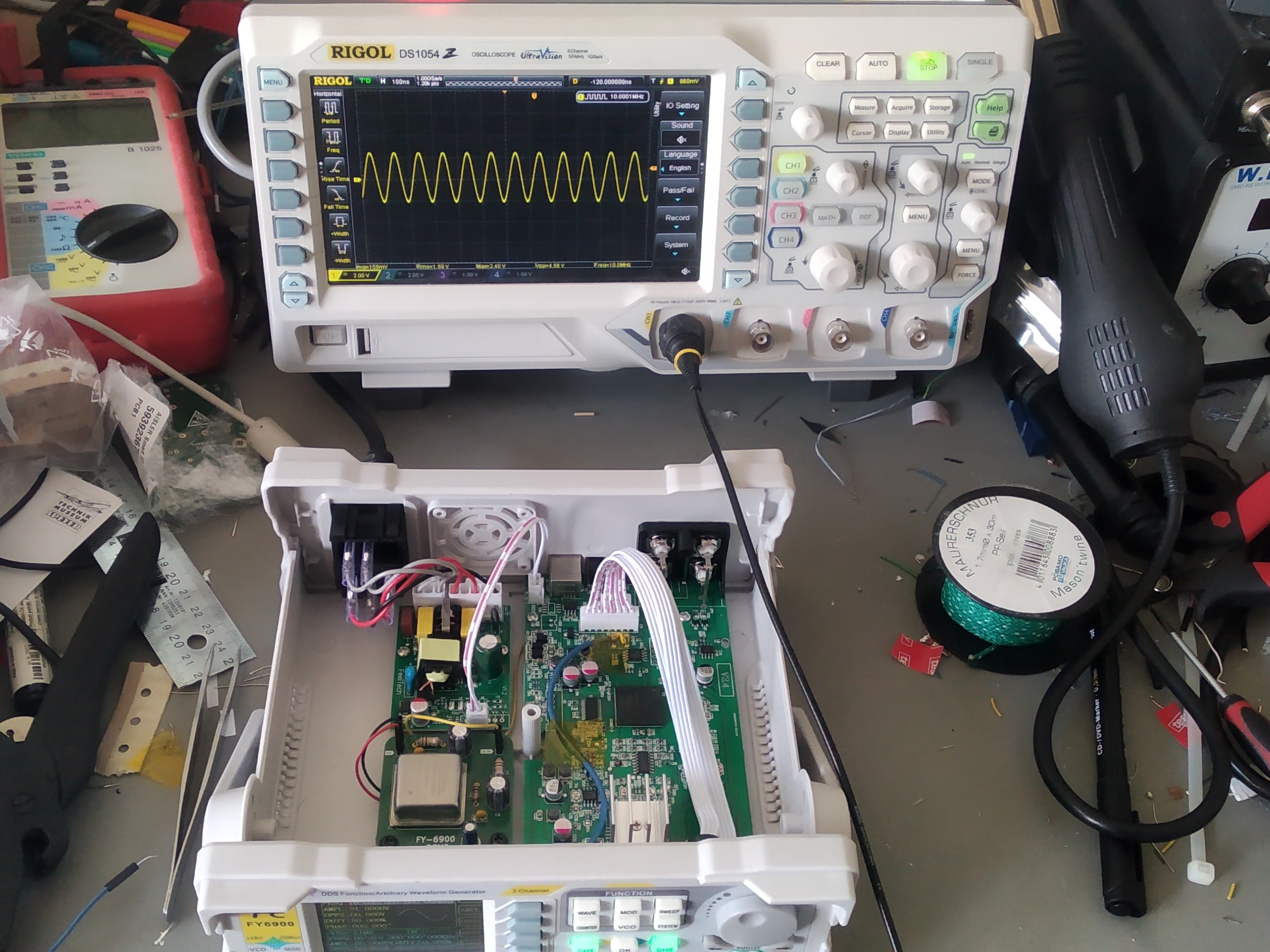
The final board also has the nice little tweak that the trimmer direct faces one of the holes that are covered by the handle. So it is possible (with some practise) to tweak the frequency after removing the handle without actually opening up the signal generator.
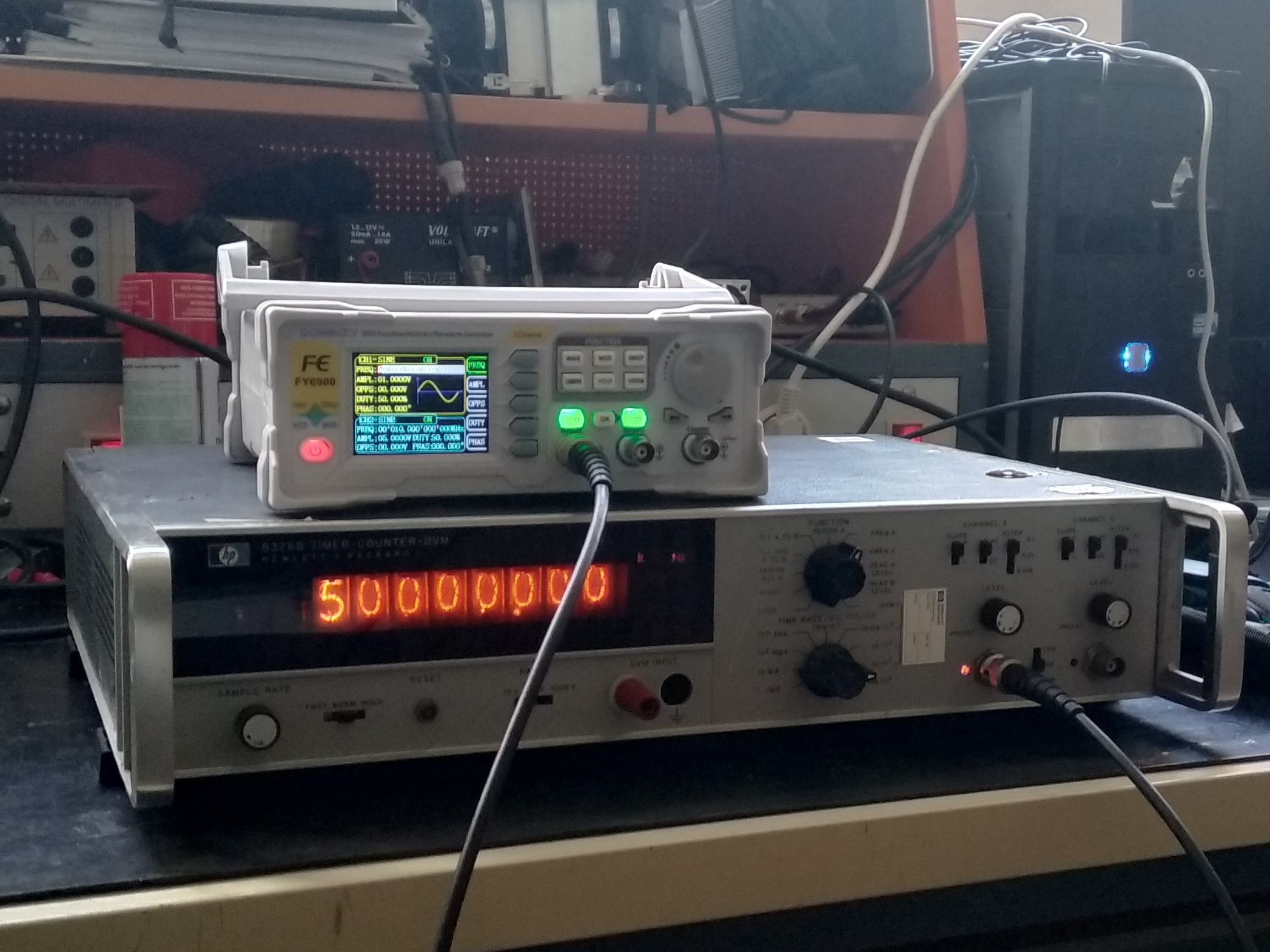
For the final frequency adjustment I needed a trustworthy source for a reference frequency. Back then we had a Trimble Thuderbolt in the DL0XK shack, along with a HP5326B frequency counter (those nixie tubes make all the difference). After some tweaking the FY6900 was spot on. More importantly it stayed that way even regardless of temperature. When I retested it a week later, it was still within +-1Hz at 50Mhz according to the GPSDO and the frequency counter. That's probably good enough for anything I'm working on at home.
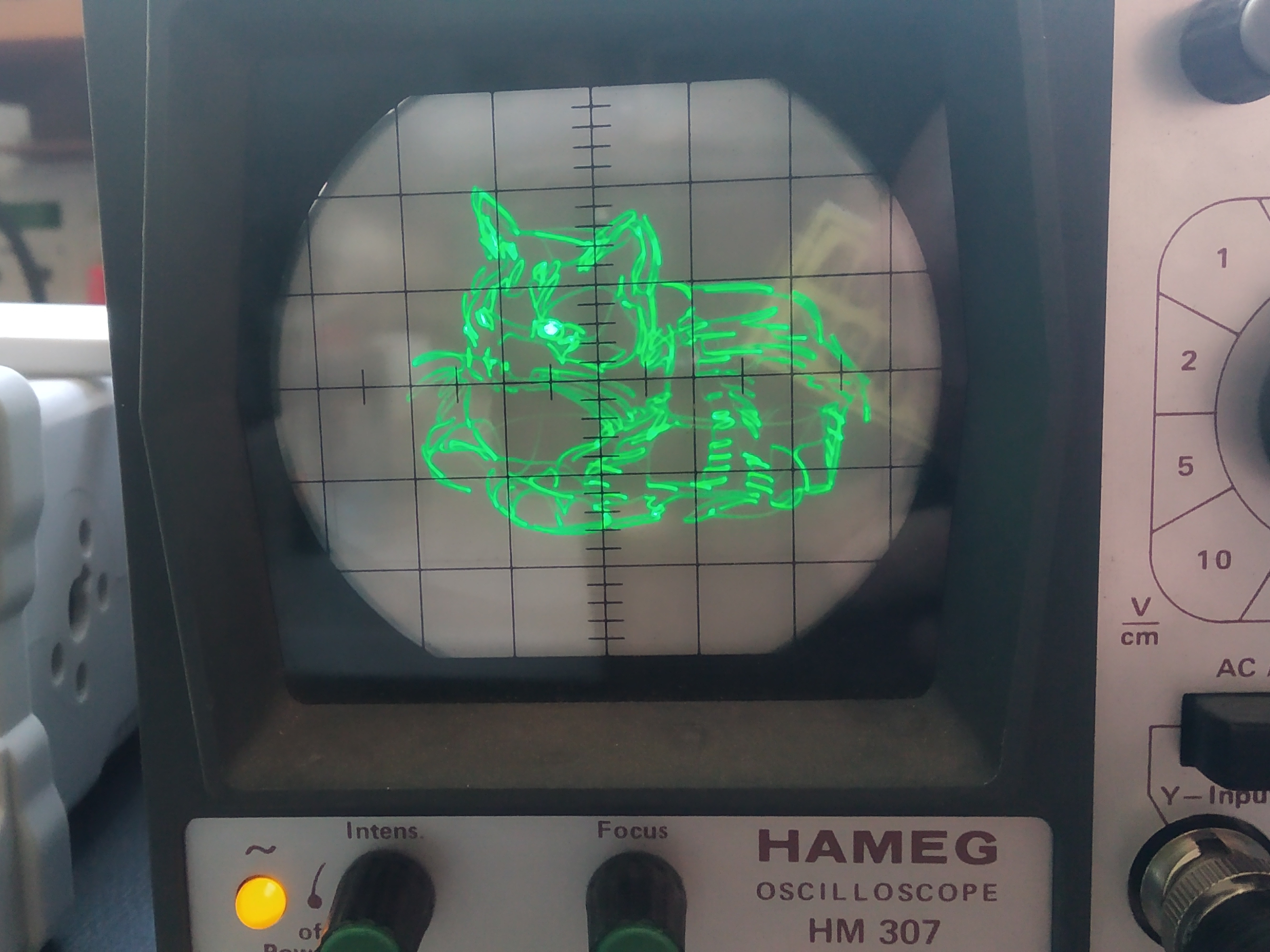
One nice feature of the FY6900 is that you can load arbitrary waveforms into it via USB. The best tool I've found for that so far is fygen.
Using fygen and an old analogue scope, we can perform the final very important Correlated Amplitude Test, which critical for determining the performance of the upgraded unit.
For comments you can use your fediverse account to reply to this toot.
Published: 30.05.2024 13:37 Updated: 31.05.2024 13:37
